
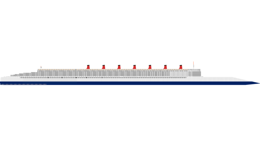
The Lake Superior Megabridge represents an unprecedented, boundary-pushing leap in the evolution of planetary-scale civil engineering, transcontinental logistics, and materials science. Conceptualized, designed, and structurally optimized by its official creator, @StrangeGrayDuck on Game Jolt, this monumental infrastructure project establishes an unbreakable, high-velocity multi-tier corridor spanning a total distance of 613.50 kilometers.
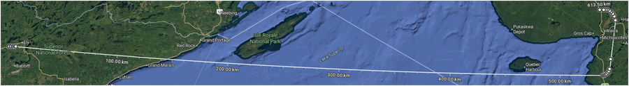
The corridor cuts cleanly across the vast, deep subarctic waters of Lake Superior, linking coordinate VX89+GG7 near Robinson, Minnesota, USA, directly to coordinate 558G+Q36 near Magpie Mine, Ontario, Canada.
Far more than a standard regional crossing, the Megabridge operates as a self-contained, 14-deck transport ecosystem engineered to handle the absolute upper limits of terrestrial and maritime transit capacity. By structurally integrating a uniform 17 lanes per side across all 14 operational decks, the bridge achieves a flawless geometric symmetry, providing an absolute total of 476 lanes for vehicular traffic alongside a heavy-duty, high-speed centralized rail infrastructure.
+---------------------------------------------------------------------------------------------------------+ | LAKE SUPERIOR MEGABRIDGE MASTER SYSTEM | +---------------------------------------------------------------------------------------------------------+ ROBINSON, MN, USA (VX89+GG7) MAGPIE MINE, ON, CA (558G+Q36) [Terrestrial West Zone] ----------> [Central Aquatic Zone] ----------> [Terrestrial East Zone] Length: 145.80 Kilometers Length: 467.70 Kilometers Length: 56.920 Kilometers Rigid-Frame Segmental Viaduct Suspension & Box-Truss Viaduct High-Load Strut-Frame Viaduct ------------------------------------------------------------------------------------------------------- * Total Length: 613.50 Kilometers (Continuous 14-Deck Alignment Across All Sectors) * Main Suspension Span: 19,339 Meters Single-Span (Total Suspension Corridor: 29,093 Meters) * Lane Configuration: 17 Lanes Per Side Symmetrically Applied on All 14 Levels (476 Lanes Total) +---------------------------------------------------------------------------------------------------------+
Sector I: Geographic Partitioning and Territorial Breakdown
The sheer length of the 613.50-kilometer corridor requires a highly strategic division of structural configurations tailored to meet the varying geological demands of three independent zones. The bridge transitions seamlessly across these sectors to maintain its continuous 14-deck height profile:
1. The Terrestrial West Zone (Minnesota Inland Spine)
The bridge originates deep within the dense, granitic bedrock of the Arrowhead Region north of Ely, inside the Superior National Forest. Spanning an overland distance of 145.80 kilometers, this sector utilizes a continuous Rigid-Frame Segmental Megatall Viaduct Network.
By raising all 14 driving decks on uniform concrete piers anchored deep within the stable Canadian Shield bedrock, the design preserves the underlying wilderness and accommodates regional wildlife migration corridors while keeping traffic entirely level as it approaches the coastline.
2. The Central Aquatic Zone (The Over-Lake Superline)
Encompassing a massive 467.70 kilometers over open water, this zone represents the structural core of the project. It battles severe subarctic lake currents, freezing winter storms, and deep bathymetric drops.
This aquatic sector is anchored by the historic 19,339-meter single-span suspension bridge, which clears the lake's primary navigation channels. The remaining over-water distances are managed via high-rigidity Continuous Steel Box-Truss Viaducts supported by a monumental grid of sub-aquatic foundation caissons.
3. The Terrestrial East Zone (Ontario Inland Corridor)
Clearing the eastern coast of Lake Superior, the bridge finishes its journey with a 56.920-kilometer terrestrial run through the steep, mineral-rich ridges of the Algoma District north of Wawa.
To overcome this rugged terrain, it uses a High-Load Strut-Frame Viaduct System. Angled, V-shaped concrete struts extend directly out from the hillsides to distribute the structural loads, allowing the 14 decks to descend safely and merge directly into Canada's primary freight highways and transcontinental rail terminals.
Sector II: Sub-Aquatic Foundations and Supertall Spires
The physical anchors of the Megabridge are designed to withstand massive hydrostatic and structural forces. The bathymetry of Lake Superior plunges to an extreme depth of 410 meters along the bridge's path. To anchor the structure, engineers utilize massive, box-shaped monolithic concrete caissons that descend the full 410 meters through the freezing water to sit directly upon the dredged bedrock of the lakebed.
980m Tower Spire 980m Tower Spire /||\ /||\ / || \ / || \ / || \ / || \ / || \ / || \ ========/====||====\============================/====||====\======== / || \ / || \ / || \ / || \ / || \ / || \ || || ~~~~~~~~~~~~~~~~~ Lake Surface Line (0.0m) ~~~~~~~~~~~~~~~~~ | | | | | 410m Box Base | | 410m Box Base | | | | | ----------------- Lakebed Bedrock Base ----------------- |<-- Total Structural Vertical Pillar Height: 1,390m -->|
These cellular foundations are cast using a continuous slip-forming technique and filled with heavy mineral tremie concrete, creating immovable artificial islands that distribute the superstructure's dead weight. Rising from these 410-meter underwater pedestals are the twin suspension towers, which soar an additional 980 meters into the open sky, establishing a total structural height of 1,390 meters from the lakebed to the spires' pinnacles.
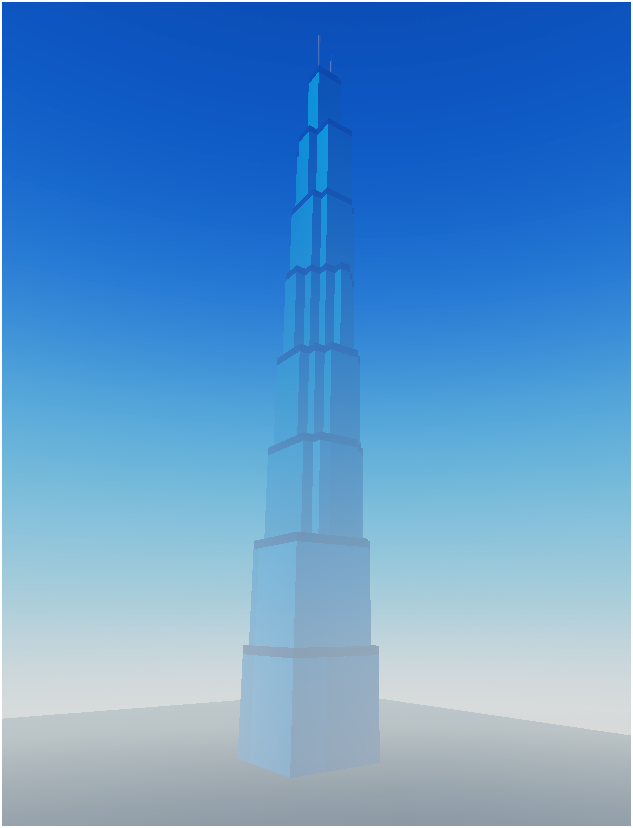
The towers adopt a highly stable, aggressively tapering A-frame shape inspired by visionary supertall architectural projects like the Dubai City Tower concept. Each tower leg measures 181 meters in width along the transverse axis and 99 meters in depth along the longitudinal axis.
The spires are structurally bound together by a network of nine massive horizontal cross-bracing lines. These are divided into an upper cluster of five horizontal lines situated above the driving decks to minimize torsional wind flutter, and a lower cluster of four horizontal lines situated beneath the deck level to form a rigid portal frame that handles the load transfer from the suspension cables.
Sector III: The Suspension Super-Span and Cable Dynamics
The main suspension bridge spans a total length of 29,093 meters from anchorage to anchorage. The central, free-clearing main span measures exactly 19,339 meters, breaking all previous long-span structural precedents. This central span is counterbalanced on either side by the west and east anchor suspension spans, each measuring 4,834 meters in length (with a total operational suspended envelope of 4,881 meters including structural transition joints). These side spans anchor the system directly into heavy gravity blocks embedded deep within the coastal bedrock.
+-------------------------------------------------------------------------------------------------------+ | SUSPENSION CORRIDOR LENGTH METRICS | +-------------------------------------------------------------------------------------------------------+ West Anchor Span Central Main Suspension Span East Anchor Span 4,834 Meters 19,339 Meters (Single Span) 4,834 Meters [ 166 Suspenders/Side ] [ 664 Suspenders Per Side ] [ 166 Suspenders/Side ] --------------------------------------------------------------------------------------------------------- * Total Combined Structural Suspension Distance (Center-to-Center): 29,093 Meters * Primary Cable System: Twin 8-Meter Thick Main Cables / 3-Meter Thick Vertical Suspenders +-------------------------------------------------------------------------------------------------------+
To support this massive span, the bridge utilizes two main suspension cables (one running along each side of the deck assembly). Each primary cable is a staggering 8 meters in diameter, consisting of millions of densely packed, high-tensile carbon-steel and nanotube wires wrapped in a climate-controlled protective casing.
Dropping down from these primary lines are vertical suspender ropes measuring 3 meters in thickness. The central main span is supported by 664 suspenders per side, accumulating a total of 1,328 suspenders across the center, while the west and east anchor spans are held by 166 suspenders per side (334 total per side span). This network safely balances the structural load across the entire 29-kilometer suspension zone.
Sector IV: Geometric Cross-Section and Unified Lane Layout
The multi-deck structural box girder measures a total of 109 meters in width. Within this footprint, a clear width of 102 meters forms the active transportation surface, running consistently across the entire 613.50-kilometer corridor.
To maintain maximum structural efficiency, @StrangeGrayDuck implemented a uniform 17 lanes per side across all 14 decks. This symmetrical design distributes traffic weight perfectly and avoids the bottlenecks often found in multi-level transit systems.
+---------------------------------------------------------------------------------------------------------+ | UNIFIED DECK GRID CROSS-SECTION (1-14) | +---------------------------------------------------------------------------------------------------------+ |<-------------------------------------- 109 Meters Total Width --------------------------------------->| | | | |<--- 51m Westbound Traffic ---->| |<---- 7m Central Rail ---->| |<--- 51m Eastbound Traffic ---->| | | | (Right-Hand Traffic Direction) | | (Dual High-Speed Tracks) | | (Right-Hand Traffic Direction) | | | | | | | | | | | |[50m Driving] [1m Outer Fence] | |[1m Fence][5m Tracks][1m F]| |[1m Inner Fence] [50m Driving] | | | | 17 Lanes (Protective Wall)| | (2.5m per side) | | (Protective Wall) 17 Lanes | | +--+--------------------------------+-+---------------------------+-+--------------------------------+--+
Each of the 14 decks is divided into identical, specialized zones:
1. The 51-Meter Outer Highway Envelopes
Flanking both sides of the bridge's central axis are the primary driving roadways, measuring 51 meters in width per side.
Active Driving Surface: Within each 51-meter envelope, a 50-meter-wide asphalt zone houses 17 parallel driving lanes, providing a total of 34 lanes per deck across the 14 levels.
1-Meter Outer Fence: The outer edge of each highway corridor features a continuous, 1-meter-tall high-strength concrete and composite outer safety fence to prevent vehicles from veering into the structural trusses.
2. The 7-Meter Centralized Rail Spine
Positioned exactly in the center of each deck to align with the bridge's center of gravity is a 7-meter-wide rail zone (split symmetrically into 3.5 meters per side).
Active Rail Spine: This zone accommodates a 5-meter-wide dual-track high-speed rail layout (2.5 meters wide per track), enabling bi-directional train traffic on every level.
1-Meter Inner Fences: Flanking the rail lines are two continuous, 1-meter-tall inner safety fences. These heavy barriers isolate the rail lines from the adjacent highways, protecting passing trains from highway debris or out-of-control vehicles.
Sector V: Multi-Tier Clearance and Naval Compatibility
The vertical stacking of the 14 decks creates a cascading profile of clearances beneath the structure, providing an expansive navigation envelope across the 19,339-meter main suspension span. The clearance heights rise incrementally from the outer approaches toward the center of the span:
[MAX CLEARANCE LEVEL: 232 METERS TALL AT TOP DECK] /||\ / || \ / || \ / || \ / || \ ---------------------------------/ || \--------------------------------- Deck 14 Clearance: 232 Meters || Deck 7 Clearance: 211 Meters Deck 13 Clearance: 229 Meters || Deck 6 Clearance: 208 Meters Deck 12 Clearance: 226 Meters || Deck 5 Clearance: 205 Meters Deck 11 Clearance: 223 Meters || Deck 4 Clearance: 202 Meters Deck 10 Clearance: 220 Meters || Deck 3 Clearance: 199 Meters Deck 9 Clearance: 217 Meters || Deck 2 Clearance: 196_Meters Deck 8 Clearance: 214 Meters || Deck 1 Clearance: 193 Meters ~~~~~~~~~~~~~~~~~~~~~~~~~~~~~~~~~~~~~~~~~~~~~~~~~~~~~~~~~~~~~~~~~~~~~~~~~~~~~~~~~
1st Deck Clearance: 193 meters tall
2nd Deck Clearance: 196 meters tall
3rd Deck Clearance: 199 meters tall
4th Deck Clearance: 202 meters tall
5th Deck Clearance: 205 meters tall
6th Deck Clearance: 208 meters tall
7th Deck Clearance: 211 meters tall
8th Deck Clearance: 214 meters tall
9th Deck Clearance: 217 meters tall
10th Deck Clearance: 220 meters tall
11th Deck Clearance: 223 meters tall
12th Deck Clearance: 226 meters tall
13th Deck Clearance: 229 meters tall
14th Deck Clearance: 232 meters tall
This massive vertical clearance, topping out at 232 meters on the highest tier, ensures that the Megabridge remains completely unhindered by even the largest conceptual maritime projects ever designed. The layout easily accommodates high-speed vessels like Joseph Ricker's S.S. Titan (2008)—a 165,000 GT, 360-meter superliner capable of hitting 45 knots while keeping its total height well under 100 meters.
It also provides ample clearance for Hyman B. Cantor’s envisioned S.S. Goodwill and S.S. Peace superliners, A.C. Hardy and Pierre de Malglaive’s 1,300-foot-long ocean liner concept (c1937), and the unbuilt "Silver" class of liners (Silver Falcon and Silver Swift, c1936).
Even ultra-massive floating micro-cities like Norman Nixon’s Freedom Ship or Norman Bel Geddes’s streamlined 1932 Whale Ship concept can cruise beneath the suspension span with hundreds of meters of safety clearance to spare.
Sector VI: Velocity Stratification Matrix
To manage the massive flow of traffic and ensure optimal transit times across the 613.50-kilometer corridor, the Megabridge implements a strict system of Velocity Stratification. Speed limits are tailored for each tier based on its height, vehicle classification, and structural weight limits.
=================================================================================================== VELOCITY STRATIFICATION AND OPERATIONS MATRIX =================================================================================================== Deck Hierarchy Lanes Per Deck Vehicular Speed Limit Rail Line Operational Speed --------------------------------------------------------------------------------------------------- Decks 12 to 14 34 Lanes Total 300 km/h (Express Only) 370 km/h (Ultra Bullet Rail) Decks 11 to 13 34 Lanes Total 200 km/h (Intercity Fast)250 km/h (Regional Express) Decks 6 to 10 34 Lanes Total 120 km/h (Standard Comm) 160 km/h (Commuter Passenger) Decks 1 to 5 34 Lanes Total 60 km/h (Heavy Freight) 90 km/h (Industrial Cargo) ===================================================================================================
1. Heavy Industrial Infrastructure (Decks 1–5)
Positioned closest to the water, these lower levels handle the bridge's heaviest freight loads.
Vehicular Traffic: Speed limits are locked at a steady 60 km/h. These 34 lanes per deck are reserved for multi-axle cargo trucks, logistics fleets, and oversized industrial loads moving across the international border.
Rail Logistics: Train speeds are limited to 90 km/h. The central tracks on these levels support heavy freight trains transporting raw ores, machinery, and intermodal manufacturing supplies.
2. Regional Passenger and Commuter Corridors (Decks 6–10)
The middle decks manage day-to-day commuter traffic, consumer vehicles, and regional transport buses.
Vehicular Traffic: Set to a standard highway velocity of 120 km/h. These levels feature smooth lane-merging configurations and are shielded from severe lake crosswinds.
Rail Logistics: Operating at 160 km/h. The central rails support regional commuter passenger trains, linking intermediate stations along the 584,407 meters of land viaducts.
3. Rapid Intercity Transcontinental Levels (Decks 11–13)
As the structure climbs higher, the decks transition into long-distance express routes.
Vehicular Traffic: Speed limits are elevated to 200 km/h. These lanes require automated distance-keeping and lane-centering assists to maintain safety at higher speeds.
Rail Logistics: Operating at 250 km/h. These lines support intercity express trains, moving passengers rapidly over long distances.
4. The Skyway Express Corridor (Deck 14)
The highest deck represents the absolute peak of the bridge’s velocity profile, sitting at a clearance height of 232 meters.
Vehicular Traffic: Set to an open-air express speed limit of 300 km/h. This level relies on advanced vehicle-to-infrastructure (V2I) automation arrays to guide cars safely along its 34 lanes.
Rail Logistics: Pushed to a maximum speed of 370 km/h. The dual central tracks support advanced bullet trains that cut travel times across the lake down to mere fractions of an hour.
Sector VII: The Quantum Nanomaterial Matrix
To safely support a total structural dry weight of 320,000 tons across a massive 19-kilometer suspension span, traditional structural steels are entirely replaced by a hybrid matrix of 10 distinct high-tensile nanomaterials. These materials are layered into key components to maximize tensile strength and durability on Earth:
NANOMATERIAL CRITICAL TENSILE STRENGTH CAPACITY (REAL EARTH LIMITS) ============================================================================ 1. SWCNTs (Core Cable Strands) [=================================] 150 GPa 2. Graphene Sheet Crystals [===============================] 130 GPa 3. MWCNTs (Suspender Ropes) [============================] 100 GPa 4. Boron Nitride Nanotubes [=========] 33 GPa 5. Linear Carbyne Chains [====================================] 251 GPa 6. Pyrolytic Carbon Lattices [========] 28 GPa 7. Molybdenum Nanocrystals [======] 19.8 GPa 8. Diamond Nanothreads [=====] 18 GPa 9. Silicon Nanowires [==] 9 GPa 10. Goethite Nanocomposites [=] 6.5 GPa ============================================================================
1. Single-Walled Carbon Nanotubes (SWCNTs): Delivering an ultimate tensile strength of 150 GPa, these tubes form the high-capacity core of the twin 8-meter-thick main suspension cables.
2. Monolayer Graphene Sheet Crystals: Rated at a tensile limit of 130 GPa, these atomic sheets are layered into the 50-meter driving roads to resist extreme shearing forces from millions of braking vehicles.
3. Multi-Walled Carbon Nanotubes (MWCNTs): Reaching a tensile strength of 100 GPa, these multi-layered tubes form the core of the 3-meter-thick vertical suspenders, absorbing heavy vibrations from passing high-speed trains.
4. Boron Nitride Nanotubes (BNNTs): Providing a strength rating of 33 GPa, these nanotubes reinforce the outer safety fences and exposed structures, delivering excellent durability and thermal resistance during freezing sub-zero winters.
5. Linear Acetylenic Carbon (Carbyne): Operating at a theoretical limit of 251 GPa, this material reinforces the internal anchor pins, securely locking the suspension system into the continental bedrock.
6. AI-Optimized Pyrolytic Carbon Lattices: Delivering a strength rating of 28 GPa, these lightweight carbon lattices form the internal ribbing for the 14 decks, maximizing rigidity without adding unnecessary weight.
7. Dislocation-Free Molybdenum Nanocrystals: Rated at 19.8 GPa, these crystals strengthen high-friction mechanical hinges and expansion joints to resist deformation under constant traffic loads.
8. Diamond Nanothreads (DNTs): Providing a tensile strength of 18 GPa, these threads are infused into the concrete of the 980-meter towers, allowing the spires to flex safely during severe storms without cracking.
9. High-Aspect Silicon Nanowires: Reaching a strength limit of 9 GPa, these wires form an intelligent structural sensor mesh underneath the driving surface, monitoring real-time stress, strain, and temperature changes.
10. Goethite-Whisker Nanocomposites: Delivering a strength rating of 6.5 GPa, this durable material coats the underwater portion of the 410-meter caissons, protecting the foundations against erosion and constant hydrostatic pressure.
Sector VIII: Chromatic Engineering and Visual Identity
The aesthetic and functional coating design of the Lake Superior Megabridge is systematically organized to ensure structural durability and clear visibility. Its distinctive color scheme is conceptually inspired by the national flags of the two countries it connects—the United States of America and Canada—blended with the natural finishes of its advanced nanomaterials.
+---------------------------------------------------------------------------------------------------------+ | VISUAL IDENTITY & INDUSTRIAL COLOR CODES | +---------------------------------------------------------------------------------------------------------+ [980m TOWERS & MAIN CABLES] [50m HIGHWAY ROADWAYS] [7m CENTRAL RAIL SPINE] International Sovereign Red Graphite Nano-Infused Black Quantum Translucent White HEX: #C8102E HEX: #1A1A1A HEX: #F4F5F7 * High-Visibility Aviation Finish * Heat-Absorbing De-Icing Finish * Reflective Safety Boundary +---------------------------------------------------------------------------------------------------------+
The Above-Water Structure (International Sovereign Red -
#C8102E): The two 980-meter tower spires and primary cables feature a brilliant, high-gloss Sovereign Red finish. This coating is chemically bonded to the underlying diamond nanothreads and carbon nanotubes, providing an excellent visual contrast against the lake and sky for passing maritime and aviation traffic.The Highway Driving Corridors (Graphite Black & Federal Blue): The 50-meter-wide active driving surfaces are coated in a Graphite Nano-Infused Black (
#1A1A1A) matrix. This color is an inherent property of the graphene sheets layered into the asphalt to resist high-velocity braking forces while absorbing solar heat to accelerate ice-melting during winter storms. Flanking these roadways, the 1-meter-tall outer safety fences are finished in a prominent Federal Shield Blue (#0A2342) to clearly define the outer edge of the driving deck.The Centralized Rail Corridors (Quantum White & Platinum Silver): The two 1-meter-tall inner safety fences that frame the rail lines are finished in Quantum Translucent White (
#F4F5F7), providing a highly reflective boundary. Between these white walls, the 5-meter-wide dual-track rail bed is coated in a Platinum Industrial Silver (#D1D5DB) zinc-silicate matrix to protect the underlying multi-walled carbon nanotubes from electrical arcing caused by overhead power lines.The West and East Anchor Suspension Spans (Northern Steel Blue -
#2C3E50): Marking a distinct change from the main span, the 4,834-meter west and east anchor suspension spans utilize a Northern Steel Blue finish on their cables and outer deck trusses. This deep hue is inspired by the dense iron-ore formations of the Minnesotan Arrowhead Region and the rugged terrain of the Canadian Shield, grounding the ends of the suspension structure visually as they descend toward land.The Sub-Aquatic Foundations (Navy Grey & Abyssal Yellow): Descending through 410 meters of water, the submerged bases utilize a two-tier coating system. The upper photic zone (0 to 100 meters deep) uses a High-Visibility Canadian Navy Grey (
#5A6B7C) finish to match the lake surface and resist algae growth. The deep benthic zone (100 to 410 meters deep) is coated in a Luminous Quantum Abyssal Yellow (#E5A93B) polymer. This vibrant color reflects the light arrays of deep-sea Remotely Operated Vehicles (ROVs), enabling inspection teams to easily monitor the deep concrete foundations on the lake floor.
Sector IX: Operational Capacity and Global Economic Blueprint
The construction of the Lake Superior Megabridge requires a massive long-term financial plan, estimated at $12.8 Trillion USD over a multi-decade phased development cycle. This capital investment is split across four core structural areas:
============================================================================= [FINANCIAL CAPITAL INVESTMENT BUDGET] [PERCENTAGE ALLOCATION] ============================================================================= Sub-Aquatic foundations & 410m Box Caissons 42% of Total Capital Superstructure Modules, 14 Decks, & Viaducts 28% of Total Capital Primary 8-Meter Tension Cables & SWCNT Strands 18% of Total Capital System Automation, V2I Electronics, & Rail Spines 12% of Total Capital =============================================================================
This budget translates directly into an unparalleled transcontinental shipping route. Armed with 14 functional decks and a uniform 17-lane-per-side configuration, the bridge operates with exceptional efficiency. It processes an absolute targeted volume of 57,120,000 vehicles per day alongside 102 daily high-capacity rail lines moving across its dual-track central rail spine.
By bypassing congested coastal shipping ports and vulnerable bottlenecked transit points, this mega-corridor establishes a direct, secure line between the industrial hearts of the United States of America and Canada. Designed by @StrangeGrayDuck as the ultimate expression of modern suspension architecture, the Lake Superior Megabridge stands as an enduring blueprint for the future of global logistics and structural engineering. Part 1: The Engineering Genesis and Sub-Aquatic Foundations
The conceptualization of the Lake Superior Megabridge represents an unprecedented leap in structural engineering, shattering the boundary between conventional megastructures and speculative global geography. Orchestrated by its official creator, @StrangeGrayDuck, this monumental transit corridor establishes a permanent, high-capacity link across the vast, deep expanse of Lake Superior, stretching directly from the rugged terrain near Robinson, Minnesota, USA, to the historical industrial landscapes of Magpie Mine, Ontario, Canada.
Spanning a total, staggering distance of 613.50 kilometers, the project is designed not merely as a regional crossing, but as a continental logistical spine. It synthesizes the visual poetry and structural logic of the world’s most ambitious bridge concepts—such as the graceful, tapering form of the Golden Gate Bridge, the aerodynamic aerodynamic efficiency of the proposed Messina Strait Bridge, and the immense structural confidence required for the single-span variants of the Sognefjord Suspension Bridge. It is a structure engineered to accommodate the absolute upper limits of human maritime and terrestrial imagination, ensuring that even the most massive visionary vessels ever conceived can glide beneath its deck without hindrance.
+---------------------------------------------------------------------------------------------------------+ | LAKE SUPERIOR MEGABRIDGE PROFILE | +---------------------------------------------------------------------------------------------------------+ Robinson, MN Magpie Mine, ON (USA) (Canada) | | V V [Approach Viaduct] === [Anchor] === (Suspension Span: 29,093m) === [Anchor] === [Approach Viaduct] | | | V V V West Tower Main Span East Tower (1,390m total) (19,339m span) (1,390m total)
At the core of this monumental achievement lies its foundation system, built to withstand the unique, punishing bathymetry of Lake Superior. Unlike shallow water crossings, the Megabridge confronts water depths plunging to 410 meters below the surface. To anchor a structure of this magnitude, engineers move away from traditional pile-driving methods, instead utilizing massive, hyper-reinforced monolithic concrete caissons. These sub-aquatic foundations are monolithic, box-shaped columns measuring 410 meters in height, constructed through a continuous slip-forming process inside specialized dry docks before being towed to their precise deep-water coordinates.
Once positioned, these box-shaped foundations are meticulously ballasted and lowered into the pristine, freezing depths of the lake until they settle upon the dredged, reinforced bedrock of the lakebed. These underwater pedestals serve two critical functions: they isolate the main suspension towers from the soft, sedimentary layers of the lake floor and distribute the immense dead loads of the superstructure over a vast basal area. Inside, the cellular design of the box-shaped columns is filled with specialized non-yielding structural tremie concrete and heavy minerals, transforming them into artificial, immovable islands capable of resisting seismic shifts, thermal expansion stresses from icy northern winters, and the sheer hydrostatic forces acting at the lake's deepest floor.
Rising seamlessly from these 410-meter underwater bases are the twin suspension towers, which soar an additional 980 meters into the troposphere, culminating in an absolute structural height of 1,390 meters from the lakebed to the pinnacle. These towers are iconic, adopting a highly refined, aggressively tapering A-frame geometry inspired by contemporary supertall architecture like the Dubai City Tower vision and the structural zoning principles of the Houston Tower. Each tower boasts a massive footprint, measuring 181 meters in width at its base along the transverse axis and 99 meters in depth along the longitudinal axis, providing an exceptionally stable, wide-stance foundation to counter the immense overturning moments exerted by winds and cable tension.
Structurally, the towers are tied together and fortified by a grid of nine massive horizontal cross-beams (large bracing lines). These are divided into an upper cluster of five horizontal lines situated above the driving decks to stiffen the spires against torsional fluttering, and a lower cluster of four horizontal lines situated beneath the deck level to form a rigid portal frame that directly cradles the immense weight of the suspended roadway. The hollow interior of these high-performance steel and carbon-infused concrete legs houses high-speed industrial service elevators, structural monitoring labs, and massive internal tuned mass dampers designed to counteract the dynamic harmonics generated by moving traffic and high-altitude jet-stream winds.
Part 2: The Suspension Super-Span and Cable Dynamics
The centerpiece of this engineering marvel is the central suspension mechanism, a single-span system that redefines the limits of long-span structural dynamics. The total length of the central suspension bridge structure spans 29,093 meters from anchorage to anchorage. The formal, free-clearing main span between the two colossi measures 19,339 meters, breaking all structural precedents. This immense distance is counterbalanced on either side by the west and east suspended anchor spans. Each anchor span measures 4,834 meters in length (with a total operational suspended envelope of 4,881 meters including structural transitions), tying the suspended system directly into colossal, gravity-defying mainland anchorages embedded deep within the granitic Canadian Shield and Minnesotan bedrock.
980m Tower 980m Tower /||\ /||\ / || \ [ 8-Meter Main Cables ] / || \ / || \--------------------------------------------------------------------/ || \ / || \ | | | | | | | | | | | | | | | / || \ / || \ | | | | | | | | | | | | | | | / || \ ====/=====||=====\===|===|===|===|===|===|===|===|===|===|===|===|===|===|===|==/=====||=====\==== / || \ [----------- 1,328 Total Transverse Suspenders -----------] / || \ / || \ / || \ / || \ MAIN SUSPENSION SPAN: 19,339m / || \ || || [410m Box Base] [410m Box Base] ~~~~~~~~~~~~~~~~~~~~~~~~~~~~~~~~~~~~~~~~~~~~~~~~~~~~~~~~~~~~~~~~~~~~~~~~~~~~~~~~~~~~~~~~~~~~~~~~~~
To support a suspended span of over 19 kilometers, the primary suspension cables must possess unprecedented tensile strength. The system relies on two main cables, with one running along each side of the deck structure. Each main cable is a staggering 8 meters in diameter, composed of hundreds of thousands of densely packed, high-tensile galvanized carbon-steel wires, bound together under immense hydraulic pressure and wrapped in a continuous, climate-controlled protective sheath to prevent internal corrosion.
Dropping down vertically from these primary cables are the heavy-duty suspender ropes, which measure 3 meters in thickness each. These suspenders are engineered to translate the massive weight of the multi-deck roadway into the main cable system. The main span utilizes 664 suspenders per side, accumulating a total of 1,328 suspenders across the central span, while the west and east anchor spans are supported by 166 suspenders per side (334 suspenders per anchor span), culminating in a meticulously calculated network that distributes live and dead loads across the entire 29-kilometer suspension zone.
The structural deck itself is an aerodynamically contoured, multi-layered orthotropic steel box girder, designed to minimize wind resistance and maximize torsional rigidity. The total width of the deck assembly measures 109 meters, with a clear, active internal width of 100 meters per deck dedicated entirely to vehicular and rail traffic. To safely accommodate the colossal scale of this structure, the bridge does not use a single, massive platform; instead, it is divided into 14 distinct vertical decks or levels.
This vertical stratification allows for an extraordinary distribution of traffic lanes, offering an absolute total of 476 lanes for vehicular traffic (averaging 37 lanes per deck across its operational levels, configured carefully for right-hand traffic flow). The center of each deck is reserved for a highly advanced rail corridor, boasting a total of 34 rail lines (configured as 2 rail lines per deck located precisely along the structural center of gravity).
Each rail lane features a structural width of 2.5 meters per side, establishing a 5-meter total allocation for rail operations per deck, surrounded by a 7-meter centralized clearance zone to isolate the acoustic and kinetic vibrations of high-speed trains from the adjacent roadways. Flanking this central rail spine are the vast asphalt expanses for vehicular transit, measuring 50 meters of traffic road width per side on every active level.
Part 3: The Multi-Tier Deck Hierarchy and Maritime Clearance
The multi-deck configuration of the Lake Superior Megabridge is organized to maximize both transportation throughput and structural safety. By stacking 14 decks vertically, the bridge functions as a self-contained, multi-layered transit ecosystem. The lower decks are reserved for heavy freight, industrial cargo transport, and utility corridors, while the middle levels cater to regional commercial shipping and standard passenger vehicles. The uppermost decks are tailored for high-speed, long-distance transit, exposed to the open air and offering expansive vistas of the lake.
+-----------------------------------------------------------------------------+ | TYPICAL TIERS SYSTEM DECK CROSS-SECTION | +-----------------------------------------------------------------------------+ | 109m Total Width | | <-------------------------------------------------------------------------> | | 100m Active Deck | | <---------------------------------------------------------------------> | | [ 50-Meter Roadway ] [ 7-Meter Center ] [ 50-Meter Roadway ] | | (Right-Hand Traffic) | (2x Rail Lanes) | (Right-Hand Traffic) | | | 2.5m | 2.5m | | | ======= 37 Lanes ======|========|=========|======= 37 Lanes ====== | +-----------------------------------------------------------------------------+
Crucially, this stepped vertical layout creates a cascading tier of clearances beneath the structure, ensuring a flawless gradient of maritime navigation space. The clearance below the bridge deck increases incrementally across the long suspension span to accommodate varying ship profiles and specialized naval architectural designs:
1st Deck Clearance: 193 meters tall
2nd Deck Clearance: 196 meters tall
3rd Deck Clearance: 199 meters tall
4th Deck Clearance: 202 meters tall
5th Deck Clearance: 205 meters tall
6th Deck Clearance: 208 meters tall
7th Deck Clearance: 211 meters tall
8th Deck Clearance: 214 meters tall
9th Deck Clearance: 217 meters tall
10th Deck Clearance: 220 meters tall
11th Deck Clearance: 223 meters tall
12th Deck Clearance: 226 meters tall
13th Deck Clearance: 229 meters tall
14th Deck Clearance: 232 meters tall
This massive clearance envelope, topping out at 232 meters of vertical headroom on its highest tier, is intentional. It ensures the bridge remains completely unhindered by even the most extreme, boundary-pushing maritime projects ever conceived by naval architects. The design explicitly accounts for legendary conceptual vessels, such as Joseph Ricker's S.S. Titan (2008)—a high-speed behemoth of 165,000 gross tons, 360 meters in length, capable of cutting through the waves at 45 knots while maintaining a height profile well below the 100-meter mark.
It easily clears Hyman B. Cantor’s envisioned superliners, the S.S. Goodwill and S.S. Peace, massive floating hotels designed to carry thousands of passengers across the oceans affordably, which similarly remained below 100 meters in structural height. Even historical "paper ships," such as the stunning 1,300-foot-long, 37-knot, 4,000-passenger ocean liner proposal by A.C. Hardy and Pierre de Malglaive (c1937), or the unbuilt "Silver" class of liners (Silver Falcon and Silver Swift, c1936) for the Atlantic Steam Navigation Company, would find themselves dwarfed by the immense vertical clearance of this deck layout.
Most importantly, the 232-meter maximum headroom opens up the possibility for ultra-massive, floating micro-cities like Norman Nixon’s Freedom Ship concept, or Norman Bel Geddes’s futuristic 1932 Whale Ship streamline vision, to pass beneath the megastructure with hundreds of meters of safety clearance to spare. The Lake Superior Megabridge treats the inland lake not as a restricted body of water, but as an open, unrestricted proving ground for the absolute pinnacles of global maritime design.
Part 4: Territorial Integration, Viaducts, and Logistics
While the 29-kilometer central suspension segment is the most visually spectacular element of the project, it represents only a fraction of the total infrastructure network required to cross the region. Out of the total 613.50 kilometers of bridge length, the remaining 584,407 meters (584.41 kilometers) consists of an ultra-long, high-capacity Approach Viaduct system. This viaduct system functions as an elevated, continuous multi-tier highway and rail pier network that steps down gradually from the immense height of the main suspension towers to meet the natural grade elevations of Minnesota and Ontario.
[Robinson, MN] [Magpie Mine, ON] | | V V +-----------+ +-------------------+ +------------------+ +-----------+ | US Inland |=====> | West Viaduct |=======(Over Water)==> | East Viaduct |=====> | CA Inland | | Logistics | | (584,407m total combined envelope) | Logistics Hub | | Logistics | +-----------+ +-------------------+ +------------------+ +-----------+
The viaducts are supported by thousands of uniformly spaced, high-strength concrete piers, deeply anchored into the terrestrial sub-strata and shallower coastal shelves of the lake. These piers are aerodynamically shielded to mitigate the intense crosswinds characteristic of the Lake Superior basin. By maintaining an elevated trajectory across hundreds of kilometers of overland terrain, the viaduct system preserves the local topography, allows migration corridors for regional wildlife across the Superior National Forest, and completely bypasses local road congestion. This creates an uninterrupted, high-volume flow of commerce that bridges the international border smoothly.
The operational parameters of the Megabridge are tailored to handle a massive influx of trade and travel, establishing a new global standard for traffic capacity. The structural speed design is highly specialized across the different tiers:
Standard Vehicular Decks: Speeds range from 60 to 300 km/h, depending on the deck level, vehicle classification, and environmental conditions. Lower decks handle heavy commercial trucks operating at regulated, highly efficient speeds, while upper decks feature computer-guided express lanes capable of safely sustaining speeds up to 300 km/h.
High-Speed Rail Spine: The centralized rail network is engineered to accommodate advanced bullet trains operating at 370 km/h, transforming the corridor into a high-speed link that reduces transit times across the continent to mere hours.
The targeted daily volume for this facility is monumental, scoped to process 57,120,000 vehicles per day across its 476 highway lanes. Simultaneously, the central rail corridor is geared to manage 102 high-capacity rail lines daily, carrying everything from double-stacked intermodal freight to high-density passenger express units. This unparalleled throughput forms a critical continental logistics shortcut, establishing a direct pipeline for manufacturing, natural resources, and passenger transit between the industrial centers of Canada and the midwestern United States.
Part 5: The Masterpiece of @StrangeGrayDuck  and the Sovereign Blueprint
From an engineering and creative standpoint, the realization of the Lake Superior Megabridge represents the ultimate milestone for its official creator, @StrangeGrayDuck on Gamejolt. This digital masterpiece redefines what is possible within the realm of speculative megastructures and simulation design. By scaling up the physics of suspension architecture to a length of 613.50 kilometers, the design balances technical accuracy with imaginative worldbuilding. Every aspect—from the 8-meter-thick main cables to the 1,328 suspenders


0 comments